
CNC Precision Manufacturing for Reliable Custom Parts


CNC precision manufacturing is used to produce metal and plastic components that require controlled dimensions, repeatable geometry, and consistent surface quality. CNC machines follow programmed cutting paths, but accurate results still depend on much more than the equipment itself.
Material condition, part geometry, fixture stability, tool wear, machining sequence, and inspection methods all influence the finished component. For buyers, understanding these variables makes it easier to prepare practical drawings, define critical tolerances, and avoid unnecessary manufacturing cost.
How CNC Precision Manufacturing Controls Part Quality
Precision begins with the drawing. Critical dimensions, datum surfaces, hole positions, thread specifications, and surface requirements should be clearly identified before machining starts.
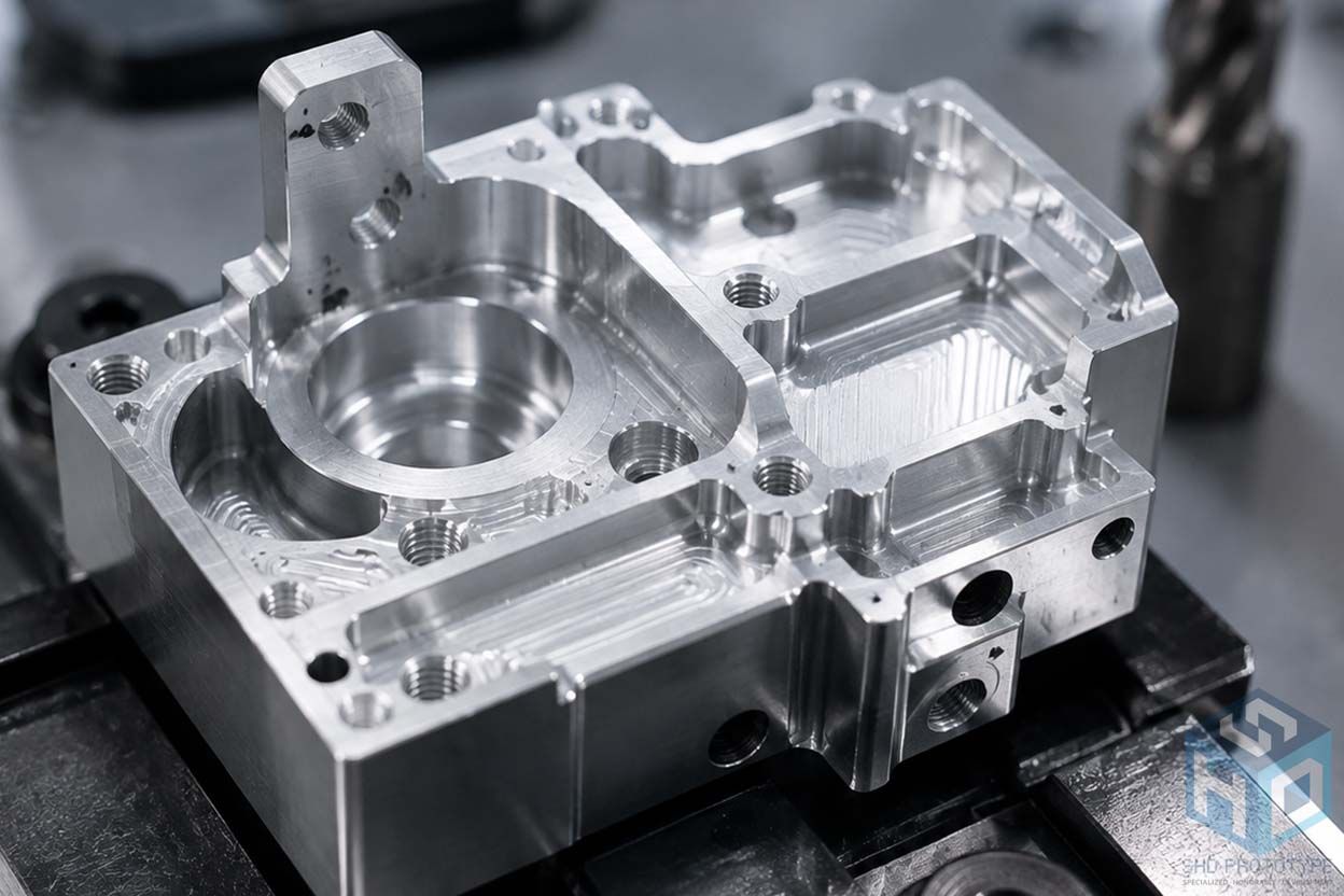
Applying very tight tolerances to every feature is not always necessary. It can increase programming time, machining steps, tool changes, and inspection work without improving part function. Tolerances should therefore focus on features that affect assembly, movement, sealing, alignment, or load transfer.
Part geometry also affects machining stability. Thin walls may vibrate or deform under cutting and clamping forces. Deep cavities can limit tool reach, while narrow internal corners may require smaller tools and longer machining times. Sudden wall thickness transitions can also create uneven stress after material removal.
Material Behavior and Machining Sequence
Different materials require different cutting strategies. Aluminum alloys, stainless steel, titanium alloys, engineering plastics, and tool steels do not respond to heat, cutting pressure, or tool wear in the same way.
During machining, heat can temporarily change part dimensions. Internal stress in rolled, forged, extruded, cast, or heat-treated stock may also be released as material is removed.
For parts requiring substantial material removal, rough machining and finish machining may be separated. The first operation removes most of the excess material while leaving a controlled allowance. Final machining is then completed after the part has stabilized. This sequence can be especially useful for thin, flat, asymmetrical, or tolerance-sensitive components.
Fixtures and Tools Affect Repeatability
A fixture must hold the workpiece securely without causing deformation. Excessive clamping force may distort thin sections, while weak or unstable support can lead to vibration, dimensional variation, and visible tool marks.
Tool condition must also be monitored. A worn cutter can gradually change hole size, edge quality, surface finish, and dimensional consistency across a batch.
Parts requiring several setups need a clear datum strategy. Every time a component is repositioned, another alignment variable is introduced. Reducing unnecessary setups can improve repeatability and shorten production time.
Inspection Should Match the Drawing
Inspection methods should be selected according to the tolerance and feature being checked. Calipers, micrometers, height gauges, thread gauges, optical systems, and coordinate measuring equipment may be used for different purposes.
Critical features such as bearing positions, sealing faces, threaded holes, mating surfaces, and assembly datums normally require more attention than non-functional surfaces.
The drawing should also clarify whether final dimensions apply before or after anodizing, plating, heat treatment, or other surface finishing. These processes may affect dimensions and should be considered when machining allowances are planned.
Conclusion
CNC precision manufacturing depends on the coordinated control of design, material behavior, tooling, fixtures, machining sequence, and inspection.
A clear drawing and realistic tolerance plan help protect important dimensions without adding unnecessary processing cost. Early manufacturability review can also identify thin walls, difficult tool access, unstable clamping areas, and finishing risks before production begins.
Precision Machining Support from SHD PROTOTYPE
SHD PROTOTYPE supports custom machined parts based on customer drawings, three-dimensional models, material requirements, critical tolerances, surface expectations, and order quantities.
By reviewing the project before machining, SHD PROTOTYPE can help identify practical machining sequences, fixture considerations, finishing allowances, and inspection priorities. This supports a smoother transition from prototype development to repeatable component production.